A few years ago, I performed an upgrade to the stock brake set-up on my 2007 Porsche Cayman S, utilizing aftermarket rotors from Girodisc and race-oriented pads from Pagid. I wrote about it in this prior blog post:
brake-upgrade-for-cayman-s

I have been extremely happy with the amazing performance of the brake set-up and also with the longevity of the rotors, which have lasted my several seasons of track days (about 10-12 track days per year). So when the rotors got down to minimum width specs and it was time to replace them, I had no doubt I would again use Girodisc rotors which are slightly larger than the stock rotors, seem to dissipate heat more readily, and don't have cracking problems when used in high-temperature, hard-braking track conditions.
When I went to purchase new rotors, I was pleasantly surprised to realize that Girodisc developed their rotors so that the ring, or disc portion of the rotor can be replaced separately from the "hat" portion which attaches to the axle assembly and ultimately the wheel. What this meant was that instead of purchasing $2200 worth of new rotors ($1100 for each set of two), I could purchase only the ring/discs for $700 for a set of two, for $1400 total. That $800 difference was a nice surprise and represents almost the cost of a new set of tires! So, I ordered the rings and started taking apart the old brakes to prepare to re-assemble the new ones. That is when I discovered that I couldn't find any online resources that showed me exactly how to complete the job, so I started taking some photos along the way to share with anyone else who might do this.
First steps were to get the car up on jack stands and remove the old brakes, then I set out the new front and rear rotor parts where they need to go (fronts and rear are different sizes and left and right are labeled from the vendor). Note that left and right are different to ensure the proper rotation of the rotor and the cooling grooves cut into the disc. See the Girodisc site for more info on that here:
girodisc.com/Technical-Info
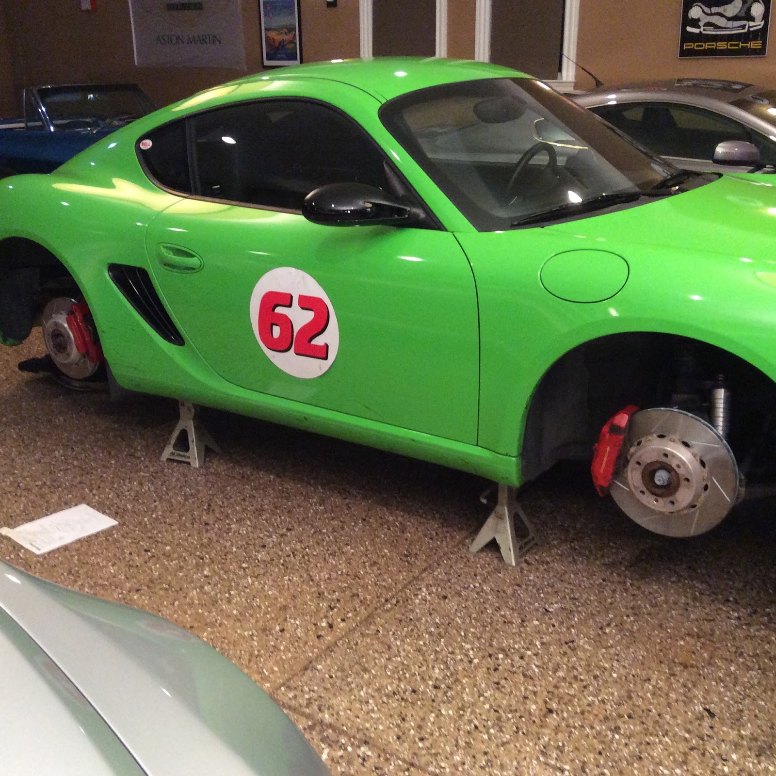
If you have never removed your Cayman brakes, it is pretty simple (at least on the 987 version of the car in 2007). With wheels off, use pliers to remove the cotter pin that holds in the retaining pin in place over the brake pads, then tap the retaining pin out from the holes at the top of the brake pads, releasing them from the small tensioner plate and remove the pads with pliers. You then remove to large bolts that hold the calipers to the axle using a T55 Torx drive socket. You then remove two small phillips head screws that hold the rotor to the axle and you can pull the rotors fully away from the axle and out of the caliper assembly. There are lots of web posts on this subject so I won't go into it any farther here. I always use some wire to then keep the calipers from dangling on their brake lines while the brakes are disassembled. It'll look something like this:


Now it was time to take the rotor "hats" off the rotor discs. This requires a 5/32 allen head wrench which will also need to be used with a torque wrench for reassembly, so it is best to just find a ratchet-driven one now for taking it apart.

I started taking them part and found a few things to note. First, the fronts were much tighter than the rears. I can only assume this is because the fronts got much hotter during their life on the track and the bolts had gone through more expansion and contraction. I was surprised at how hard it was to get the bolts off the from the hat because I knew the torque settings to reassemble were only 5 ft-lbs (60 inch-pounds).

Once the 10 bolts have been removed from the inside of the hat, the hat should separate from the ring. But on the fronts, again, it didn't come away easily. The heat had them somewhat bonded, but by holding the hat I could smack the disc with a hammer to separate them. The next thing to get out were the drive bushings, which are the threaded "sleeves" that the bolts go into, the heads of which you see on the outside-facing part of the rotor.


Again, the front ones had a harder time coming out, so I used an old screwdriver as a center-punch to get them out. The rear ones came out just with with finger-power.

With the hats now removed, I used a wire brush on a drill to clean up any corrosion, and finished off with some brake-clean to make sure the hats would seat perfectly on the new rings and that the assembly would seat nicely to the axle. The people at Girodisc make sure to tell you that any burrs or inconsistencies on the contact surfaces can lead to vibration or diminished performance. The clean hats were now ready to go onto the new rings.


The hardware kit includes 10 bolts and drive bushings for each rotor, with 5 of one type of bolt assembly and 5 of another. You assemble them using these two bolts in an alternating pattern around the hat. One type has an expansion piece/spacer that looks like "shoulders" on the bolt. This sits against the hat surface and (I assume) allows for some expansion when the brakes get hot.

I first placed the brass-colored drive bushings into the hat, and found that I needed to clean up the inside circumference of the old front hats with a round file, just so the bushing went in smoothly. Just a few filings and the hat holes were ready to accept the bushings.

I then placed the hat onto the new ring, lining up the bushings into the holes on the ring and then installed the ten bolts in alternating pattern. I placed a couple drops of high-temperature thread locking fluid on each bolt. I don't have a photo there, because I didn't have three hands and I was holding the rotor assembly vertically. I then placed the rotor down flat on the bench and torqued the bolts to 60 in-lbs.

With the rotors now each re-assembled, I just reversed the process and re-installed the rotors onto the car. Of course, now you have a slightly thicker rotor disc than the old used one so you may have to push the caliper piston-pots back to a more flat position against the inside of the caliper. I use the handle portion of a large 1/2' ratchet to lay against the inside surface and control slowly how much pressure to apply to make the pistons go back into the caliper. With the rotors back on the car, note the proper orientation of the rotor grooves relative to the direction of the car.


Good luck with your brake upgrade!!